Description
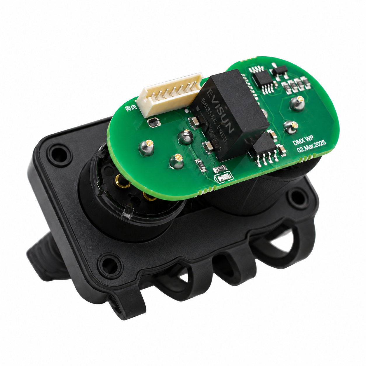
Add isolated DMX reception and passive THRU to FB4-based equipment using the waterproof 3-pin XLR connector format. Choose an electronics-assembled board for XLR assembly or a module with pre-soldered connectors. No PCB or enclosure IP rating is specified.
Choose the assembly
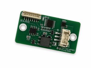
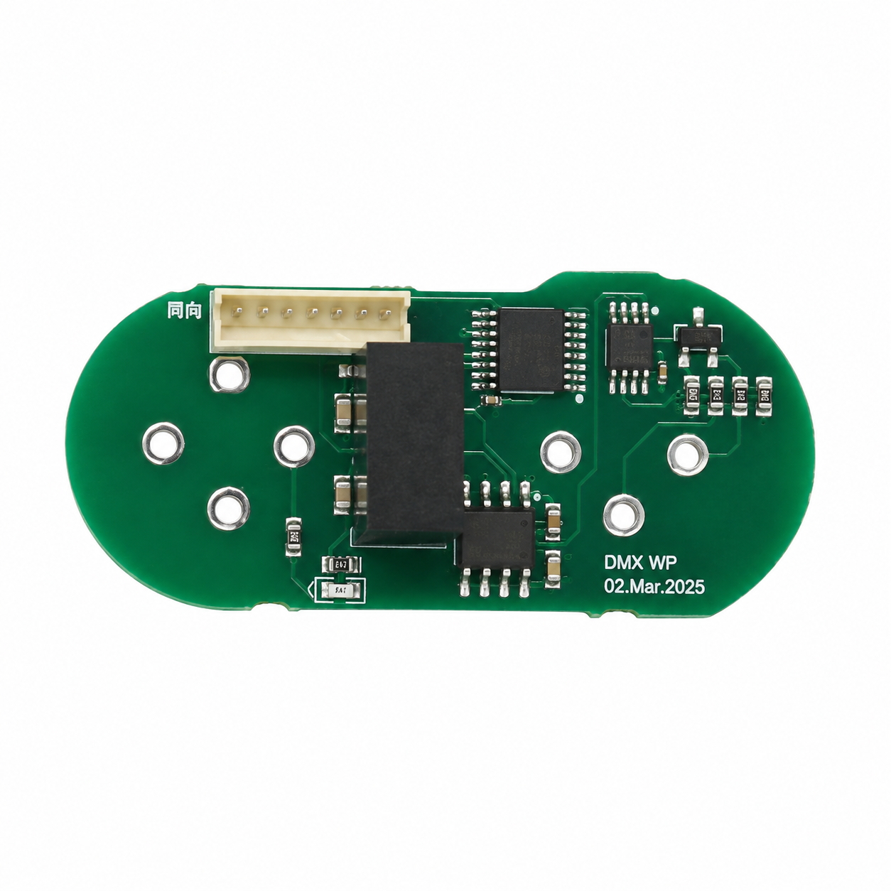
- DMX WP — Bare board: electronic components and the internal 7-pin header are assembled; the two XLR connectors are not soldered. Compatible waterproof XLR assembly and soldering are required.
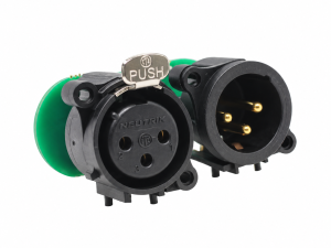
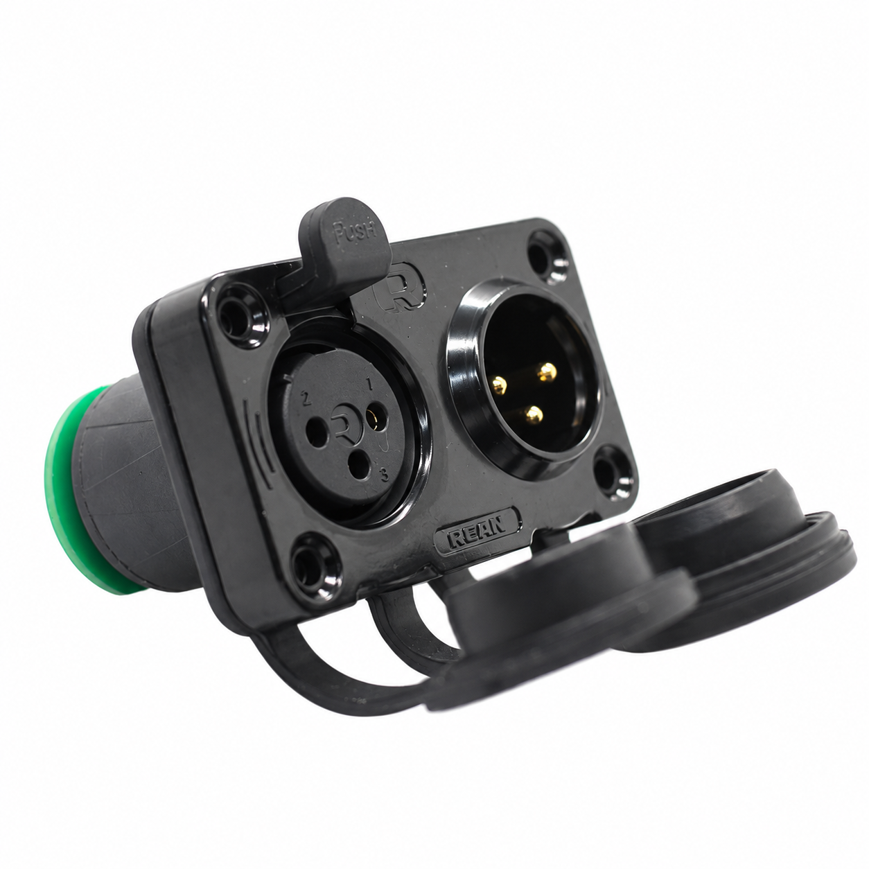
- DMX WP kit — Pre-soldered kit: the waterproof male and female 3-pin XLR assembly is soldered to the board.
Both options require a suitable enclosure, panel mounting and an FB4 internal harness. Confirm any separately supplied accessories with the order. A kit is an integration module, not a standalone controller or complete enclosure.
Technical specifications
| Application | DMX input interface for an FB4 mainboard |
|---|---|
| Input supply | Nominal 3.3 V DC through the internal 7-pin connector |
| Receive path | Isolated power and digital isolation; RO output in the 3.3 V logic domain |
| DMX IN | Male 3-pin XLR |
| DMX THRU | Female 3-pin XLR; direct passive connection |
| Termination | None onboard; use an external 120-ohm terminator between XLR pins 2 and 3 at the end of the DMX chain |
| XLR interface centre spacing | 25 mm; panel openings and fixing dimensions depend on the connector version |
| Internal interface | 7 pins, 1.5 mm pitch |
Connections and power
IN and THRU pins 1, 2 and 3 are connected directly, pin for pin. THRU works without board power. DMX reception and the RO output to FB4 require board power. This interface does not transmit, regenerate or actively repeat DMX; it is not an active splitter or a bidirectional interface.
| 7-pin contact | Signal | Function |
|---|---|---|
| 1 | GND | FB4-side power and logic ground |
| 2 | RO | Isolated DMX receive data output to FB4 |
| 3 | NC | Not connected; leave unused |
| 4 | SCL | I²C clock |
| 5 | SDA | I²C bidirectional data |
| 6 | INT | Active-low, open-drain interrupt output |
| 7 | +3.3V | Nominal 3.3 V DC supply input |
Confirm pin 1 from the PCB marking or a verified ground connection before applying power. Use the numbered connector photographs in the manual; the solder-side view is mirrored. Do not infer polarity from wire colours. The FB4 mainboard must provide suitable pull-ups for SCL, SDA and INT. Follow its documentation for the harness, firmware and menu requirements.
Both XLR ports use pin 1 for signal common/shield, pin 2 for Data− and pin 3 for Data+. Use the connector’s numbered contacts. Do not apply 5 V, 12 V or 24 V to the 3.3 V input. The internal isolated 5 V rail is for onboard circuits only and is not an external supply output.
WP panel opening and water protection
WP accepts compatible waterproof 3-pin XLR connectors with thicker pins. NWP accepts standard A-series XLR connectors with thinner pins. Circuit functions and interface pin assignments are the same, but the XLR pad-hole diameters differ. No numerical pad-hole diameter is specified; verify the connector footprint and mechanical fit.
Viewed from the rear of the panel, the WP assembly uses one connected capsule-shaped opening and four separate fixing holes. The middle must be connected so the soldered PCB assembly can pass through.
| XLR interface centres C1–C2 | 25 ±0.1 mm |
|---|---|
| Rounded opening ends | At least Ø24 mm |
| Fixing holes | 4 × at least Ø3.2 mm |
| Fixing-hole centre spacing | 44 ±0.1 mm horizontal; 24 ±0.1 mm vertical |
| Opening reference envelope | 49 mm length and 24 mm height with nominal 25 mm spacing and Ø24 ends; reference only |
The 25 mm dimension measures interface centre spacing, not fixing-hole spacing or opening length. The 49 mm reference does not imply a 49 ±0.1 mm overall-length tolerance. The drawing is an installation reference, not a 1:1 drilling template. Trial-fit the assembly, seals and panel clearance before machining.
WP identifies the waterproof connector format; no PCB or enclosure IP rating is specified. Water protection depends on the specified mating connector or cap, intact seals, panel installation, cable entries and the complete enclosure. Protect the PCB inside a suitable enclosure. Waterproof connectors alone do not establish an IP rating; no immersion capability is stated. Follow the connector manufacturer’s installation guidance and inspect caps, seals, latches and panel fixings regularly.
Installation and checks
Disconnect FB4 and DMX power before assembly, installation or handling the internal harness. Verify the connector footprint and harness pin assignment. For the bare-board option, fit and align the male IN and female THRU connectors before soldering; inspect the solder joints and check pin-to-pin continuity and supply shorts.
Mount the assembly so the panel or enclosure carries connector insertion forces. Secure the internal harness without strain on the PCB or header. Check polarity, soldering and insulation before power-up. Test FB4 reception with a known working DMX source, then test the next device through THRU. The onboard LED indicates isolated-side power, not DMX activity.
Grounding and isolation
The isolation boundary is between the DMX receive field side and the FB4 power and logic side. IN and THRU are directly linked and are not isolated from each other.
External grounding paths can bypass isolation. FG is chassis/frame ground; GND is the internal FB4-side ground; GND-ISO is the DMX-side ground (XLR pin 1). If local FG is bonded to GND and XLR pin 1 also reaches local FG through a connector shell or interconnected equipment and a common FG path, the external path bypasses the isolation barrier. DMX reception may still work, but the two sides are no longer galvanically isolated. Normal reception does not prove isolation.
Before installation, with power off and normal FG/PE bonds and system connections retained, check FG–GND, XLR pin 1–shell and GND-ISO–GND continuity. Never disconnect protective earth (PE) to restore isolation. Do not rely on a bypassed isolation barrier to block ground-loop currents or protect internal circuitry.
Isolation component specifications are 3.75 kVrms (3750 Vrms) for 60 s for signal isolation, and 1500 VDC for 60 s for isolated power. These are separate component test values, not continuous working voltages or tested complete-board ratings; do not add them. Complete-board withstand and working isolation voltage are not specified. See manual page 6 for the conditions and additional component parameters.
Manuals and technical scope
Use the English manual for the exact model selected: v1.7, issued 5 October 2026, six pages. Page 3 identifies the 7-pin connector orientation; page 5 gives the version-specific panel openings; page 6 covers isolation ratings and external grounding bypass risk.
Board current, operating temperature range, cable length, node count, complete-board isolation withstand and overall mechanical dimensions outside the stated panel drawing are not specified. Verify mechanical fit against the actual assembly before machining.
International shipping is quoted for your destination and quantity, with a minimum charge of USD 20.
Ordering and packing
Prices are per individual board or pre-soldered module. Kits with XLR connectors are packed up to 16 per carton; bare boards are packed up to 50 per carton. Standard and waterproof variants can share cartons within the same assembly type. Boards and kits are packed separately. International shipping is calculated at checkout from the number of cartons needed, with a minimum charge of USD 20.