Description
FB4NW — Five-Port Ethernet Switch Board with Direct FB4 Header
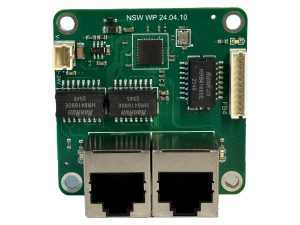
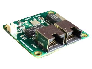
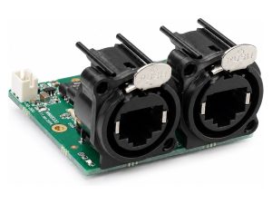
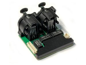
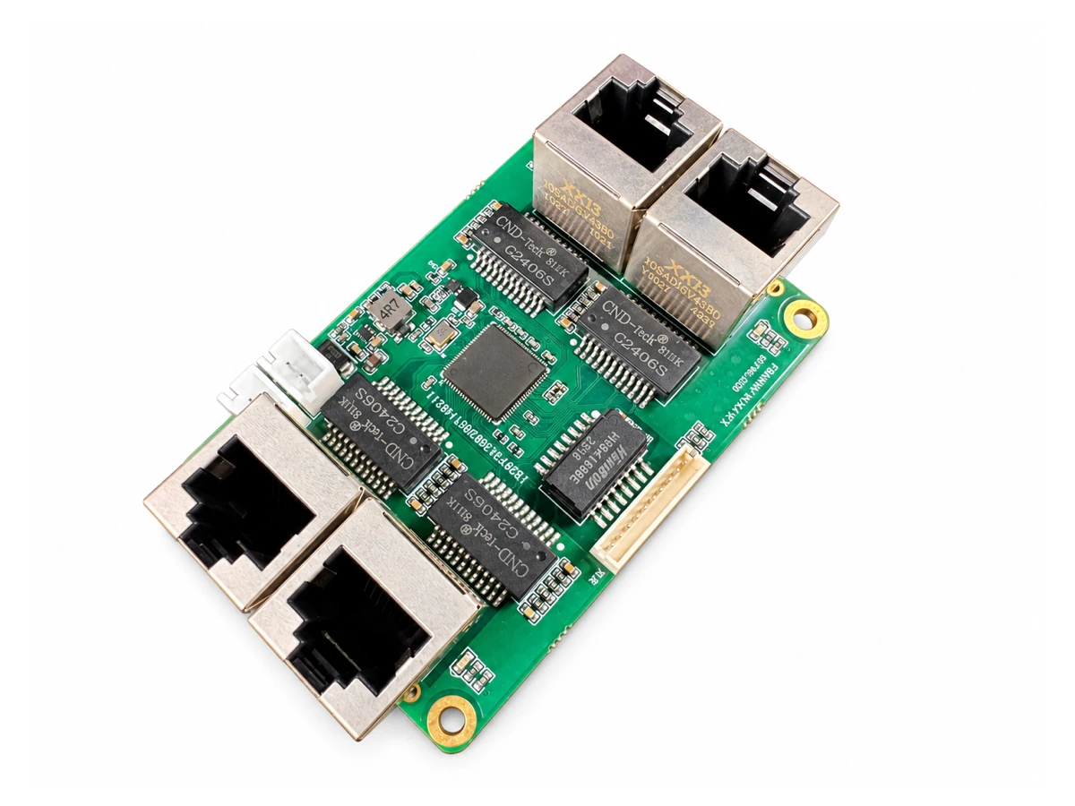
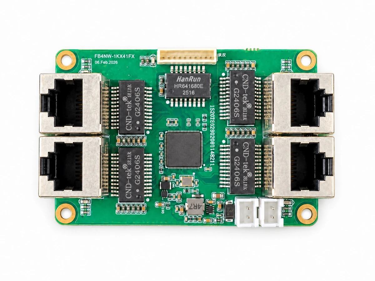
FB4NW is a network switch board for laser projectors, fixture housings and OEM show-control equipment. Four RJ45 network connectors and a separate 10-pin FB4 header provide five network paths on a 49 × 73 mm PCB.
Sold individually; order any quantity from one board. Order code: FB4NW.
Features
- Five network paths — four RJ45 connectors plus a dedicated FB4 header.
- Four gigabit-capable RJ45 design paths — four-pair Ethernet connections at each RJ45 port.
- Direct FB4 connection — 10-pin, 1.50 mm pitch header with a separate two-pair 100M design path.
- Recommended DC 5–24 V input — use a regulated supply; suitable for nominal 12 V and 24 V systems.
- Two parallel power headers — J2 and J3 share the same supply nets.
- Compact six-layer PCB — 49 × 73 mm with R2.5 mm corners.
- Four mounting holes — Ø3.2 mm plated holes on a 43 × 67 mm centre-to-centre pattern.
- Five on-board status LEDs.
Specifications
| Model / order code | FB4NW |
|---|---|
| RJ45 connections | 4 × RJ45; four-pair gigabit design paths |
| FB4 connection | J4: 10-pin, 1.50 mm pitch; two-pair 100M design path |
| Recommended input | Regulated DC 5–24 V; nominal 12 V or 24 V systems |
| Power headers | J2 / J3: 2 pins; pin 1 = GND, pin 2 = V+; both headers are wired in parallel |
| PCB outline | 49 × 73 mm; R2.5 mm corners; 6 copper layers |
| Mounting | 4 × Ø3.2 mm plated holes; 43 × 67 mm hole-centre spacing |
| Sales unit | 1 board; minimum order: 1 board |
| Individual packaging | 10 × 10 × 5 cm per board |
Port speeds describe the circuit design; negotiated link speed and sustained throughput have not been measured for this datasheet. The recommended supply range is derived from the circuit and component ratings. Confirm the intended FB4 controller, connector pin assignment and harness orientation before connection.
Integration
Designed for internal fixture and enclosure mounting. The bare PCBA has no ingress-protection rating; environmental protection depends on the enclosure and external connectors. J2 and J3 share the same power nets and must not be connected to independent power supplies.